×
- Live Chat
- 1-888-984-2011

My Garage
My Account
My Cart
Genuine Honda Prelude Brake Disc
Disc RotorEnter your vehicle info to find more parts and verify fitment
- Select Vehicle by VIN
- Select Vehicle by Model
Select by VIN
orEnter your VIN for the most accurate results.Enter your VIN for the most accurate results.
Select by Model
-- Select Model --
-- Select Year --
-- Select Body & Trim --
-- Select Emission & Transmission --
14 Brake Discs found
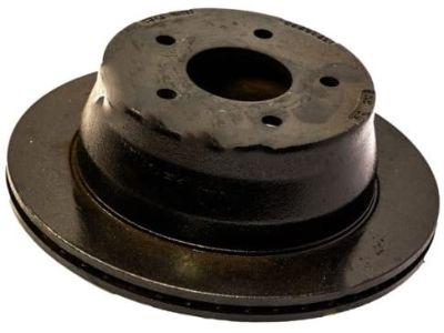
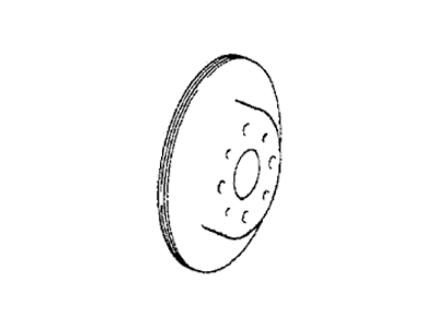
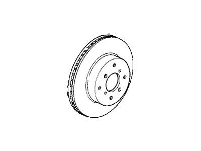
Honda Prelude Disk, Front Brake (15")
Part Number: 45251-SZ3-000- Other Name: Rotor
- Position: Front
$86.45 MSRP: $122.10You Save: $35.65 (30%)Honda Prelude Disk, Rear Brake
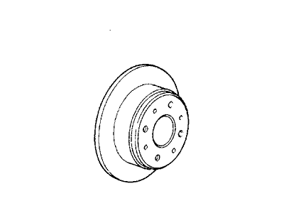
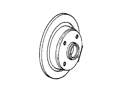
Part Number: 42510-SE0-000- Position: Rear
- Replaced by: 42510-SE0-010
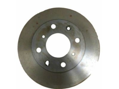
$75.51 MSRP: $106.65You Save: $31.14 (30%)Honda Prelude Disk, Front Brake
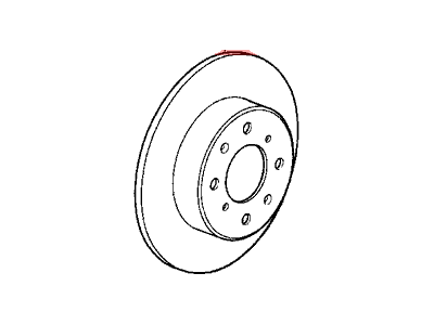
Part Number: 45251-SA6-670- Position: Front
- Replaced by: 45251-SE0-010
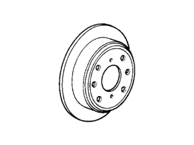
$66.65 MSRP: $94.13You Save: $27.48 (30%)Honda Prelude Disk, Rear Brake
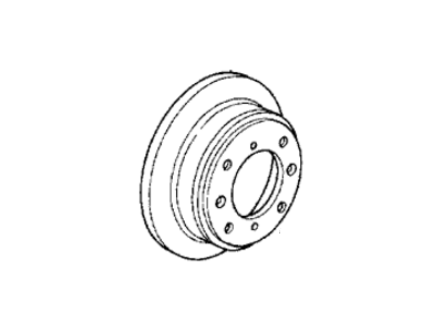
Part Number: 42510-SS0-J00- Position: Rear
- Replaced by: 42510-SS0-000
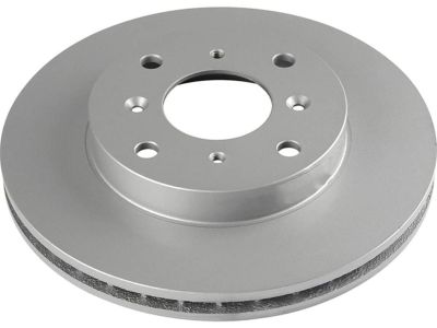
$87.83 MSRP: $124.05You Save: $36.22 (30%)Honda Prelude Disk, Front Brake
Part Number: 45251-SB0-000- Other Name: Brake Rotor; Rotor
- Position: Front
$37.49 MSRP: $54.34You Save: $16.85 (32%)Honda Prelude Disk, Front Brake
Part Number: 45251-SA5-000- Position: Front
- Replaces: 45251-693-000, 45251-692-000, 45251-SA0-660
Honda Prelude Disk, Front (14", 23T)
Part Number: 45251-S0A-940- Other Name: Rotor
- Position: Front
- Replaces: 45251-SS0-000, 45251-S1A-G60, 45251-S10-000
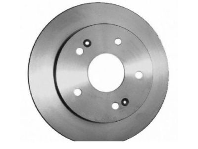
Honda Prelude Disk, Rear Brake
Part Number: 42510-SS0-000- Other Name: Rotor
- Position: Rear
- Replaces: 42510-SD4-000, 42510-SS0-J00
Honda Prelude Disk, Front Brake
Part Number: 45251-SF0-000- Other Name: Splash Shield; Rotor
- Position: Front
Honda Prelude Disk, Front Brake (15", 23T)
Part Number: 45251-SS0-A00- Position: Front
- Replaced by: 45251-S0A-000
Honda Prelude Disk, Front Brake
Part Number: 45251-SE0-010- Other Name: Brake Rotor; Rotor
- Position: Front
- Replaces: 45251-SA6-670
Honda Prelude Disk, Rear Brake
Part Number: 42510-SE0-010- Other Name: Brake Rotor; Rotor
- Position: Rear
- Replaces: 42510-SH3-000, 42510-SK3-E00, 42510-SE0-000, 42510-SH3-G00, 42510-SK7-A00
Honda Prelude Brake Disc Parts Questions & Answers
- Q: How do you remove and install Brake Disc on Honda Prelude?A: To remove and install the brake components you need to pull out or use siphon or turkey baster to pull out about half of the brake fluid from the master cylinder, then lift and provide support to the vehicle and after that, remove the tire/wheel assembly. Third, remove the caliper mounting bolts and then unbolt the caliper assembly from the brake rotor by drawing it upward off the brake rotor thus hanging it with a wire to avoid applying stress on the brake flex hose. Subsequently as the caliper body and brake pads are to be dismantled, the caliper bracket mounting bolts are to be loosened and the bracket has to be detached from the rotor. Take out the rotor retaining screws and withdraw the brake rotor straight off the wheel mounting studs, using bolts if the latter is very tight. For installation, push the piston back into the caliper if possible, follow this by fixing the brake rotor to the wheel hub and narrowly screwing tight. Bolt the caliper mounting bracket, position the caliper and pad over the rotor and bracket and fit the mounting bolts. Refill the master cylinder with new brake fluid, replace the tire /wheel assembly and then drop the vehicle. Press the brake pedal and build up pressure to give a firmer feel before any maneuver, Also perform a road test to check how the brakes work. On the 1996-97 Accord, first un-bolt the knuckle assembly, and detach the hub further, take off the splash guard, and the flange bolts before pulling to separate the hub from the brake rotor. Installation is done by reversing the process the spindle nut should be tightened to 181 ft. lbs. radiator nuts to 25 ft. lb. and the wheel lug nuts to 80 ft. During the inspection of the brake part check the rotors for any defects which may include crack or warping of the rotors. Slight scratching is allowed, deep scratching or bowing needs sanding or to be replaced. Solvent cleaning is done before installation to remove whatever protective layer that could be on new rotors. To inspect the rotor safely support the vehicle and then take out the tire/wheel assembly and then measure the run-out, thickness, and parallelism. Run out should not exceed 0.004 inches; you should use a dial indicator to determine the extent of run out. Check up on the thickness of the rotor at several regions and check with the minimum limit and change it if it is below the rates. For parallelism, find the difference between the largest and the smallest measurements; if it is more than 0.0006,'machine' the rotor. When machining leads to a size below the minimum size, then replacement is compulsory.
Related Honda Prelude Parts
Browse by Year
2001 Brake Disc 2000 Brake Disc 1999 Brake Disc 1998 Brake Disc 1997 Brake Disc 1996 Brake Disc 1995 Brake Disc 1994 Brake Disc 1993 Brake Disc 1992 Brake Disc 1991 Brake Disc 1990 Brake Disc 1989 Brake Disc 1988 Brake Disc 1987 Brake Disc 1986 Brake Disc 1985 Brake Disc 1984 Brake Disc 1983 Brake Disc 1982 Brake Disc 1981 Brake Disc 1980 Brake Disc 1979 Brake Disc
