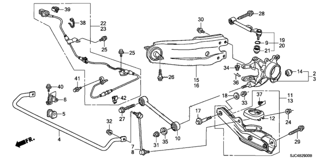
Loosen the rear wheel lug nuts, raise the rear of the vehicle, and support it securely on jack stands while blocking the front wheels to prevent rolling. Remove the wheel. If removing the rear knuckle, loosen the drive axle/hub nut. A special tool is necessary to separate the upper arm ball joint from the rear knuckle. Support the lower arm B with a floor jack under the coil spring pocket. Remove the lock pin from the castle nut on the ball joint stud and loosen the nut until there is a small gap. Install the ball joint separating tool, taking care not to damage the grease seal, and apply grease to the tool's contact points. Once the ball joint stud is released, remove the castle nut and separate the arm from the knuckle. Remove the upper arm-to-sub frame mounting bolt and then the arm. Installation is the reverse of removal, ensuring to tighten the ball joint stud castle nut to the lower torque figure and install a new lock pin. Raise the lower arm B to simulate normal ride height before tightening the arm-to-sub frame bolt and the wheel lug nuts. Support the lower arm B with a floor jack, remove the lower arm-to-sub frame mounting bolt and the lower arm-to-knuckle mounting nut and washer, then remove the arm from the vehicle. For installation, ensure the washer is installed correctly and raise the rear suspension to simulate normal ride height before tightening the fasteners and wheel lug nuts. Support the lower arm B under the shock/coil spring assembly pocket, remove the nuts/bolts securing the shock/coil spring assembly to the lower arm B, and detach the steering knuckle from lower arm B. Mark the toe adjuster cam's relationship to the sub frame, remove the pivot bolt/nut, and then remove lower arm B. For installation, align the marks, raise the outer end of lower arm B, and tighten the fasteners and wheel lug nuts, followed by checking the rear wheel alignment. Remove the parking brake shoe assembly, unbolt the brake hose and line brackets from the trailing arm, and support the lower arm B. Remove the trailing arm-to-knuckle bolts and the trailing arm-to-chassis mounting bolts, then remove the trailing arm. For installation, tighten all fasteners to the proper torque specifications, and check the rear wheel alignment if necessary. Remove the parking brake shoe assembly, then on 4WD models, remove the drive axle/hub nut and discard it; on 2WD models, remove the axle shaft from the hub. Unbolt the brake hose bracket from the trailing arm and the brake line bracket from the knuckle, then remove the ABS wheel speed sensor and harness from the knuckle. Support the lower arm B, detach the upper arm, lower arm A, trailing arm, and lower arm B from the knuckle. On 4WD models, carefully push the drive axle while removing the knuckle, using a puller if necessary. For installation, tighten the ball joint stud castle nut to the lower torque figure, install a new lock pin, and a new drive axle/hub nut. Raise the lower arm B and tighten the fasteners and wheel lug nuts, followed by tightening the drive axle/hub nut to the specified torque.

")
")
")

")
")

")

")