×
- Hello
- Login or Register
- Quick Links
- Live Chat
- Track Order
- Parts Availability
- RMA
- Help Center
- Contact Us
- Shop for
- Honda Parts
- Honda Accessories
My Garage
My Account
Cart
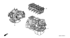
Genuine 2000 Honda Prelude Transmission Assembly
Trans Assembly- Select Vehicle by Model
- Select Vehicle by VIN
Select Vehicle by Model
orMake
Model
Year
Select Vehicle by VIN
For the most accurate results, select vehicle by your VIN (Vehicle Identification Number).
3 Transmission Assemblies found

 Product Specifications
- Other Name: Transmission Assembly (Automatic)
- Item Weight: 141.90 Pounds
- Item Dimensions: 25.2 x 21.0 x 20.5 inches
- Condition: New
- Fitment Type: Direct Replacement
- SKU: 20021-P6H-A10
- Warranty: This genuine part is guaranteed by Honda's factory warranty.
- Product Specifications
- Other Name: Transaxle
- Item Weight: 103.80 Pounds
- Item Dimensions: 25.5 x 22.9 x 20.4 inches
- Condition: New
- Fitment Type: Direct Replacement
- SKU: 20011-P6J-U60
- Warranty: This genuine part is guaranteed by Honda's factory warranty.
- Product Specifications
- Other Name: Transaxle
- Replaced by: 20011-P16-Y61
- Item Weight: 111.80 Pounds
- Item Dimensions: 25.6 x 24.8 x 16.7 inches
- Condition: New
- Fitment Type: Direct Replacement
- SKU: 20011-P16-Y60
- Warranty: This genuine part is guaranteed by Honda's factory warranty.
2000 Honda Prelude Transmission Assembly
Our website is the optimal online store for when you need any genuine 2000 Honda Prelude Transmission Assembly. We offer a wide range of 2000 Honda Prelude Transmission Assembly at unbeatable prices. We will help provide you with a worry-free shopping experience at highly competitive prices. In addition, all OEM parts are backed by the manufacturer's warranty.
2000 Honda Prelude Transmission Assembly Parts Questions & Experts Answers
- Q: How to Remove and Install a Manual Transmission Assembly on a 2000 Honda Prelude?A: Always get the code number before disconnection of the battery, as the radio may also contain a coded theft protection circuit. If the vehicle is equipped with 4WS, the steering control unit turns off when the battery is disconnected, and then returns to normal when the battery is reconnected. To do this turn the steering wheel lock to lock. Start by moving the transaxle into R, disconnecting the negative battery cable then removing the battery. Next, remove the intake duct and air cleaner case, battery base, vacuum tank and bracket without disconnecting the hoses. Loosen the two upper transaxle mounting bolts then disconnect the starter wires and remove the starter. Unbolt the engine harness clamp, disconnect the transaxle ground cable and back up light switch wire, remove both shift cables from the transaxle case and wiring them out of the work area leaving both cables attached to their bracket. Remove the sensor from the transaxle case, but retain the sensor hoses. Clamp down the Vehicle Speed Sensor connector harness and detach the carrier. Remove the slave cylinder mounting bolts while leaving hydraulics line connected, remove slave cylinder from its mount with its mounting bolts still in place, move slave cylinder out of work area, being careful not to press ON the clutch pedal or kink the metal hydraulic line. The aims: Then drain the transaxle fluid and safely raise and support the vehicle. Clutch damper mounting bolts are removed and the clutch damper raised, the rear engine mount bracket stay is removed if equipped. Remove the splash shield, cotter pins and lower arm ball joint nuts, then separate the ball joints and tower arms with ball joint tool, press type. Remove the damper fork bolt and the radius rod on the right side of the vehicle, pry the right and left halfshafts out of the differential and intermediate shaft, pegged at the inboard joint to remove. While secured in plastic bags over the halfshaft inboard joints, unbolt and remove the intermediate shaft from the differential and wire the halfshafts to the underbody of the vehicle. Remove the center beam and clutch cover on vehicles with the H22A1 engine, remove the H22A1 front engine stiffener plate, then remove the H22A1 rear beam stiffener, and the intake manifold stay. Remove the three rear engine mount bracket bolts, place a transaxle jack under the transaxle then raise it enough so its weight is removed from the mounts. Next, remove the two transaxle mount and mount bracket bolts, three of the rear engine mount bracket mounting bolts and three lower transaxle housing bolts. To clear the mainshaft out and lower it off the vehicle, pull the transaxle away from the engine. To install it, new self locking nuts and set rings for the front suspension components and halfshafts plus new self locking bolts for the center beam and rear engine mount bracket can be purchaced from a honda dealer. Install dowel pins in the transaxle case, apply high temperature grease to the mainshaft splines, release fork bolt and paws, throw out bearing, install bearing and release fork, ensuring release fork goes into fully seated position. Raise the transaxle into position with a transaxle jack, install the three lower and two upper transaxle mounting bolts, and evenly tighten them to 47 ft. lbs. Install the transaxle mount and mount bracket, temporarily tighten the through-bolt, ensure the engine is level, then tighten the three bracket-to-mount nuts and two bolts to 28 ft. lbs., followed by tightening the through-bolt to 47 ft. lbs. Install the three new rear engine mount bracket bolts on the engine side and tighten them to 40 ft. lbs., then install the rear beam stiffener and tighten the bolts to 28 ft. lbs. Install the intake manifold stay and tighten the bolts to 16 ft. lbs., followed by the clutch cover and its bolts to 9 ft. lbs. On vehicles with the H22A1 engine install front engine stiffener bolts and tighten to 28 ft. lbs. with the one bolt threaded into transaxle case first, then the two bolts to the engine. Insert the center beam and tighten bolts to 43 ft lbs, then insert intermediate shaft and tighten mounting bolts to 28 ft lbs. Install new set rings on halfshaft inboard joint by splines on halfshafts and then insert halfshafts and lock them in place. Install the radius rod and damper fork, hand tight them, install the ball joint to the lower arm, castle nut 36 - 43 ft. lbs., install a new cotter pin. Then install the clutch damper, tightening the bolts to 16 ft. lbs., then put the front wheels on and lower the vehicle. Raise the vehicle so that the weight is supported by a floor jack under the right front control arm, then tighten radius rod mounting bolts to 76 ft. lbs., radius rod nut to 32 ft. lbs., tighten damper pinch bolt to 32 ft. lbs. and damper fork bolts to 47 ft. lbs. After preloading your suspension, set the vehicle on the ground and remove the floor jack. Coat the tip of the slave cylinder with heavy-duty high-temperature grease, install the clutch hose pipe and clutch slave cylinder to the transaxle housing, ensuring the slave cylinder snaps into the release fork, and tighten the slave cylinder mounting bolts to 16 ft. lbs. Install the speed sensor and tighten the mounting bolt to 14 ft. lbs., then install the shift cable and select cable to the shift arm lever, followed by the shift cable assembly onto the transaxle case, tightening the cable bracket mounting bolts to 16 ft. lbs. and installing new cotter pins. Followed by installing the harness clamp, connect the back-up light switch coupler and transaxle ground cable. Connect the starter wires, then install the starter tightening the 10mm bolt to 32 ft. lbs and the 12mm bolt to 54 ft. lbs. Remove the three front engine mount bracket bolts, loosen them, and torque them to 28 ft. lbs. Install the vacuum tank with its bracket, the air cleaner case and intake duct. Install the battery base stay and battery base, tightening the battery base bolts to 16 ft. lbs., and install the battery and connect the battery cables; check clutch pedal free-play, start the vehicle, and check the transaxle and clutch for smooth operation. To reset the steering control unit on vehicles with 4WS, turn the steering wheel lock to lock and inspect and correct the front wheel alignment, then enter the security code and check and correct as necessary if the radio security code is incorrect.
Related 2000 Honda Prelude Parts
 2000 Honda Prelude Torque Converter
 2000 Honda Prelude Valve Body
 2000 Honda Prelude Side Cover Gasket
 2000 Honda Prelude Transmission Gasket