×
- Hello
- Login or Register
- Quick Links
- Live Chat
- Track Order
- Parts Availability
- RMA
- Help Center
- Contact Us
- Shop for
- Honda Parts
- Honda Accessories
My Garage
My Account
Cart
Genuine Honda CRX Axle Shaft
Car Axle Shaft- Select Vehicle by Model
- Select Vehicle by VIN
Select Vehicle by Model
orMake
Model
Year
Select Vehicle by VIN
For the most accurate results, select vehicle by your VIN (Vehicle Identification Number).
32 Axle Shafts found

Honda CRX Driver Side Driveshaft Set
Part Number: 44011-SH3-A20$215.99 MSRP: $307.68You Save: $91.69 (30%)Honda CRX Driver Side Driveshaft Set
Part Number: 44011-SH3-000$215.99 MSRP: $307.68You Save: $91.69 (30%)
Honda CRX Passenger Side Outboard Driveshaft Set
Part Number: 44010-SB2-961$218.16 MSRP: $310.77You Save: $92.61 (30%)
Honda CRX Driver Side Outboard Driveshaft Set
Part Number: 44011-SB2-761$222.34 MSRP: $316.72You Save: $94.38 (30%)
Honda CRX Passenger Side Driveshaft Set
Part Number: 44010-SH3-A20$237.59 MSRP: $338.45You Save: $100.86 (30%)Honda CRX Passenger Side Driveshaft Set
Part Number: 44010-SH3-000$237.59 MSRP: $338.45You Save: $100.86 (30%)Honda CRX Driver Side Outboard Driveshaft Set
Part Number: 44011-SB2-960$259.27 MSRP: $369.33You Save: $110.06 (30%)


| Page 1 of 2 |Next >
1-20 of 32 Results
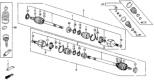
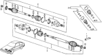
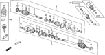
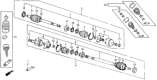
Honda CRX Axle Shaft
The Axle Shaft in Honda CRX automobiles is involved in the power transmission each wheel by a certain differential to help the wheels rotate in different planes for enhanced purchase at the times of cornering. Normally made up of high tensile steel, these axle shafts are built to work under extreme conditions of high performance driving while ensuring correct positioning of wheels and bearing capacity of the whole bearing load. Honda CRX models employ 'half-shafts' which includes joints which have splined end that interconnect with the 'differential' as well as the 'wheel hubs'. This design also goes well in the movement of power in the vehicle's independent suspension. Throughout the years, any changes which could have taken place with the axle shaft design are limited and the overall operation of the Honda CRX axle shaft is still the same even across generations. You have to ensure that it is being maintained periodically because when the CV joints are already worn out or when the axle seals are cracked, the performance of the vehicle will be affected most likely resulting to noise and feeling of vibration.
In search of affordable OEM Honda CRX Axle Shaft? Consider browsing through our extensive inventory of genuine Honda CRX Axle Shaft. Not only do we provide market-leading prices and a manufacturer's warranty, but we also pride ourselves on exceptional customer service and swift delivery.
Honda CRX Axle Shaft Parts Questions & Experts Answers
- Q: How Does Power Transfer Through the Axle Shaft and Differential System on Honda CRX?A:Power gets to the axle through the companion flange which is located on the pinion shaft. Pinion shaft and gear brings the power in to Differential and rotates at engine speed. It rotates with the help of the gear mounted at the end of pinion shaft that meshes with a large ring gear mounted with its axis of rotation perpendicular to that of the pinion. This positioning entails holding down the gear ratio of the axle, and also reversing the rotation so as turn the axle shafts that then power the two wheels. The axle gear ratio, therefore, stands for the number of pinion gear teeth by the number of ring gear teeth. The ring gear rotates the differential case: there are two bearings for the ends of a pinion shaft on which two pinion gears can be installed. These pinion gears in turn mesh with two side gears, each fitted at the inner terminus of a given axle shaft. This differential setting makes the outer axle shaft revolve at a faster rate than the inner axle shaft in the process of the turn. Per main pinion and the side bearings on which the weight of the differential case rests, preloading and correct positioning of the pinion and probably ring gears is done by adjusting the shims. Limited slip differentials are fitted with clutches which connect each axle shaft to the differential case, which engage through springs or torque pressure during a turn. On level ground and dry surface, the said clutches are disengaged and each wheel rotates as desired at the appropriate rate. However, when there is slippage on either wheel the clutches transfer some of the power to the wheel with better grip; this makes demands a special type of lubrication for the limited slip units.


