×
- Hello
- Login or Register
- Quick Links
- Live Chat
- Track Order
- Parts Availability
- RMA
- Help Center
- Contact Us
- Shop for
- Honda Parts
- Honda Accessories
My Garage
My Account
Cart
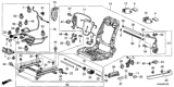
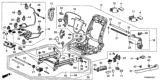
Genuine Honda Pilot Relay
Wire Relay- Select Vehicle by Model
- Select Vehicle by VIN
Select Vehicle by Model
orMake
Model
Year
Select Vehicle by VIN
For the most accurate results, select vehicle by your VIN (Vehicle Identification Number).
25 Relays found


Honda Pilot Relay Assembly, Power (Micro Iso) (Mitsuba)
Part Number: 39794-SDA-A05$22.62 MSRP: $32.22You Save: $9.60 (30%)


Honda Pilot Relay Assembly, Power (Micro Iso) (Omron)
Part Number: 39794-SDA-A03$22.62 MSRP: $32.22You Save: $9.60 (30%)


Honda Pilot Relay Assembly, Engine Control Module (Denso)
Part Number: 39794-SDA-902$66.82 MSRP: $96.83You Save: $30.01 (31%)


Honda Pilot Relay Assembly, Fuel Pump (Denso)
Part Number: 39794-SDA-004$51.60 MSRP: $73.50You Save: $21.90 (30%)


Honda Pilot Relay Assembly (Micro Iso)
Part Number: 39792-SDA-A01$5.61 MSRP: $7.91You Save: $2.30 (30%)


Honda Pilot Relay Assembly, Power (5P) (Micro Iso) (Mitsuba)
Part Number: 39794-S10-003$48.29 MSRP: $68.78You Save: $20.49 (30%)


Honda Pilot Relay Assembly, Main
Part Number: 39400-S84-003$101.61 MSRP: $143.51You Save: $41.90 (30%)

Honda Pilot Relay Assembly, Fuel Pump (5P) (Mitsuba)
Part Number: 39794-S5A-003$44.80 MSRP: $63.82You Save: $19.02 (30%)


Honda Pilot Relay Assembly, Power (Micro Iso) (Denso)
Part Number: 39794-SDA-A02$37.90 MSRP: $53.99You Save: $16.09 (30%)

Honda Pilot Relay Assembly, Power (Micro Iso) (Omron)
Part Number: 39792-SJC-A01$8.81 MSRP: $12.55You Save: $3.74 (30%)


Honda Pilot Relay Assembly, Engine Control Module (4P) (Mitsuba)
Part Number: 39794-S5A-901$45.81 MSRP: $65.25You Save: $19.44 (30%)

Honda Pilot Relay Assembly, Power (Micro Iso)
Part Number: 39794-TBA-A01$4.47 MSRP: $6.32You Save: $1.85 (30%)


Honda Pilot Relay Assembly, Power (4P No 305) (056700-9260) (Denso)
Part Number: 39792-SL4-003$69.24 MSRP: $97.80You Save: $28.56 (30%)

Honda Pilot Relay Assembly, Turn Signal And Hazard (Trico)
Part Number: 38300-S9V-A01$82.95 MSRP: $117.17You Save: $34.22 (30%)

Honda Pilot Relay Assembly, Power (4P) (056700-7410) (Denso)
Part Number: 39792-SE0-003$69.24 MSRP: $97.80You Save: $28.56 (30%)


Honda Pilot Relay Assembly, Power (4P No.305) (Denso)
Part Number: 39792-SM4-013$56.79 MSRP: $80.22You Save: $23.43 (30%)
Honda Pilot Relay Assembly, Power (5P) (Micro Iso)
Part Number: 39794-SNB-E01$38.99 MSRP: $55.06You Save: $16.07 (30%)
Honda Pilot Relay Assembly, Ignition (1) (Omron)
Part Number: 39794-TG7-A01$6.40 MSRP: $9.03You Save: $2.63 (30%)


Honda Pilot Relay Assembly, Power (4P) (Rc-2201) (Mitsuba)
Part Number: 39795-SB2-003$92.32 MSRP: $130.41You Save: $38.09 (30%)
| Page 1 of 2 |Next >
1-20 of 25 Results
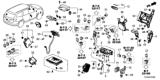
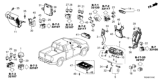
Honda Pilot Relay
The Honda Pilot Relay is an electrically controlled switch that protects and coordinates multiple climate systems in the SUV so that comfort is guaranteed even in extreme weather. By directing a low power signal to open or close high current circuits, the Relay can ensure that the fan, blower motor, and AC control system only become active when called for by the command module, helping to avoid wasted energy and premature wear. Early designs were traditionally electromechanical in nature, with a built-in electromagnet to physically move contacts, although later models may have solid state or magnetic latching styles, both of these types of devices being intended to increase reliability and response speed. Electromechanical units reset when the power goes off, while latching types maintain their position after a single pulse, which is an advantage for the Pilot when maintaining its settings in case of short power drops. No matter the style applied, it is important to replace a worn-out Relay unit on time because a failed Relay can cause an immediate silencing of the part with which it is connected, leaving the occupants without cooling or heat. Regular inspection ensures that the Honda Pilot cabin is comfortable and protects more expensive parts in the Honda system that depend on a sound switch. This little Honda part, when paired with precise Pilot electronics, makes one healthy Relay keep the whole journey pleasant.
In search of affordable OEM Honda Pilot Relay? Consider browsing through our extensive inventory of genuine Honda Pilot Relay. Not only do we provide market-leading prices and a manufacturer's warranty, but we also pride ourselves on exceptional customer service and swift delivery.
Honda Pilot Relay Parts Questions & Experts Answers
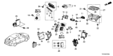
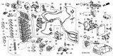
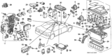
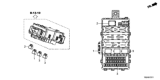
- Q: What is the function and testing procedure for relays on Honda Pilot?A:These cars have a number of electrical add-ons, such as fuel injection system, Horns, starter and fog lamps, which are controlled by relays that ensure transmission of electric signals to the respective components. By allowing low-current control circuit to open and close high-current power circuit relays function. These relays can be found in the engine compartment fuse/relay box and near the fuse and relay boxes under the dashboard. There are usually three main types: normally-open type-A , normally-open type-B, and five-terminal type ones. The internal circuitry is similar on Type A and Type B relays while they differ in external spade terminal arrangement and numbering. Compared to Type A or Type B relays, five-terminal relays have different internal circuitry plus an added external spade terminal. To test a relay it must be removed from the vehicle and an ohmmeter used to check for continuity. Normally open Type A relays for instance which are used for various purposes such as air conditioning; horns; window lifters have four external spade terminals arranged in two rows. When you unplug them from power sources you should make sure there is no connection between terminals No1 &No2 on one hand but also that there is between terminal No 3 connected to power source via (terminal No 4) a ground wire respectively.The normally-open Type B ones similarly have four external parallel rows of spade terminals just like their counterparts above mentioned for example blower motors; rear defoggers . For these B-type testing is simple which requires breaking connection between contact points No1&No3 when current ceases to flow through them whereas creating path between contacts No1&No3 using their corresponding feeds wires from connectors No2&No4 which are connected with interfaced power line as well as grounded with earth respectively.A last category we will take care about here is five-terminal devices known for moonroof control ; high beam cut-off and others need us to examine continuity between point No 1 &No 4 without power supply whereas later on it should be established by joining terminal No. 3 to power and the ground respectively provided that connection has been completed at points No2&No5. These relay switches are normally discarded as they cannot be repaired.
 (Omron)")
Related Honda Pilot Parts
 Honda Pilot Oil Pressure Switch
 Honda Pilot Brake Light Switch
 Honda Pilot Power Window Switch
 Honda Pilot Door Jamb Switch
 Honda Pilot Neutral Safety Switch
 Honda Pilot Headlight Switch
 Honda Pilot Turn Signal Switch
 Honda Pilot Seat Heater Switch
 Honda Pilot Seat Switch
 Honda Pilot Wiper Switch
 Honda Pilot Mirror Switch
 Honda Pilot Dimmer Switch