×
- Hello
- Login or Register
- Quick Links
- Live Chat
- Track Order
- Parts Availability
- RMA
- Help Center
- Contact Us
- Shop for
- Honda Parts
- Honda Accessories
My Garage
My Account
Cart
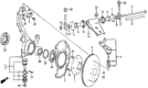
Genuine Honda Prelude Wheel Hub
Wheel Axle Hub- Select Vehicle by Model
- Select Vehicle by VIN
Select Vehicle by Model
orMake
Model
Year
Select Vehicle by VIN
For the most accurate results, select vehicle by your VIN (Vehicle Identification Number).
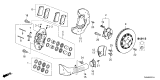
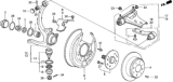
16 Wheel Hubs found


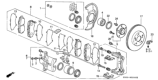
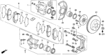
Honda Prelude Front Hub Assembly
Part Number: 44600-S47-000$234.83 MSRP: $334.52You Save: $99.69 (30%)

Honda Prelude BEARING ASSY-, RR
Part Number: 42200-T60-A01$308.62 MSRP: $439.63You Save: $131.01 (30%)
Honda Prelude BEARING ASSY-, FR
Part Number: 44200-T60-A01$369.37 MSRP: $526.17You Save: $156.80 (30%)
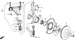


Honda Prelude Wheel Hub
The Wheel Hub is an essential component which interconnects the wheel and the vehicle to guarantee appropriate attachment and rotation. In particular, it accommodates basic components such as wheel bearing and brake thereby playing an important role in vehicle performance and steering. It is also important to note that the Honda Prelude Wheel Hub Bolt Pattern may differ from year to another with regard to bolt patterns as well as specifications that may differ for various models of the vehicle. Specifically, when fixing the Wheel Hub, it is necessary to pick the piece that can be a direct fit for the car's requirements because universal ones may not be the prime match for Honda Prelude. Replacements may be more expensive depending on the year, make or model and or components used but there are affordable OE grade products. One of the several reasons for a proper installation, nonetheless, is to avoid mechanical problems, something that can be attributed to the Wheel Hub as contributing to longevity and safety of the Honda Prelude.
In search of affordable OEM Honda Prelude Wheel Hub? Consider browsing through our extensive inventory of genuine Honda Prelude Wheel Hub. Not only do we provide market-leading prices and a manufacturer's warranty, but we also pride ourselves on exceptional customer service and swift delivery.
Honda Prelude Wheel Hub Parts Questions & Experts Answers
- Q: How to remove and install wheel hub on Honda Prelude?A:The wheel bearings are non-adjustable and non-repairable and require replacement if they are faulty. Once the hub has been removed it is difficult to replace the wheel bearings by using a hydraulic press and bearing drivers. Firstly, try to open the spindle nut stake and free the nut, it is advisable that the vehicle is on all the four wheels. There must be proper positioning of the wheel then the spindle nut can be easily detached from the vehicle. After that you can remove the caliper mounting bolts and the caliper and use wire to keep the caliper to make sure that it does not pull the brake hose. Unscrew the 6mm brake disc retaining screws and use replacement two 8×1.25mm bolts and turn the bolts two time in an anticlockwise direction to push the disc away from the hub. Lose the cotter pin and then the castle nut and finally use a remover to take off the tie rod ball joint. Half undo the nut of lower arm ball joint and then use a puller to pull the joint, carefully to avoid damaging the boots. If fitted, take off the upper ball joint shield and using a screwdriver you should pull off the cotter pin and take off the upper ball joint nut so that you can divorce the upper ball joint from the knuckle. Pull the knuckle and hub back far enough so that the halfshaft can be slid off, then undo the splash guard bolts from the knuckle. Lay the knuckle/hub assembly on a hydraulic press and put the hub under the knuckle and press the knuckle with the hub supporting it in place. It is easy to take off the splash guard and the snap ring; the hub/wheel bearing can be pressed out of the knuckle when it has been supported. If required, then the requirement of the bearing puller can be felt to remove the outer bearing inner race from the hub. To install clean the knuckle and hub, drive in a new wheel bearing to the knuckle being careful to see that the press tool blister contacts only the outer race, install the snap ring and splash shield and do not over tighten the screws. Put the hub on the press table then press the knuckles on to the hub in such a way that it only touches the inner bearing race. Place the front knuckle ring on the knuckle and fit the knuckle/hub assembly on to the vehicle, while torque to the lower ball joint nut and the tie rod end nut 32 Ft. Lbs. 120 kgf.cm for new cotter pins for the upper ball joint nut and 44 Nm for the lower ball joint nut, and 40 ft. lbs. An overhaul of the engine includes the replacement of the existing camshaft with a new one, having a new capability of force of 55 Nm in addition to installing a new cotter pin. The brake disc and caliper shown below have been fitted and tightened the caliper bracket bolts to 80 ft. lbs. I will secure jacking points 30 min-then remove the rear wheels, unscrew the bolts and tighten the nuts up to 108 Nm, install the front wheels and lower the vehicle. Last but not the least, rotate the spindle nut to 181 ft. lbs. Tighten the bolts to 245 Nm to the wheel studs and the wheel nuts to 80 ft. lbs. The average torque value recorded was 108 Nm after which, the front wheel alignment of the vehicle was checked and adjusted.

Related Honda Prelude Parts
 Honda Prelude Wheel Stud
 Honda Prelude Lug Nuts
 Honda Prelude Wheel Bearing
 Honda Prelude Spindle
 Honda Prelude Wheel Seal
Browse by Year
2026 Wheel Hub 2001 Wheel Hub 2000 Wheel Hub 1999 Wheel Hub 1998 Wheel Hub 1997 Wheel Hub 1996 Wheel Hub 1995 Wheel Hub 1994 Wheel Hub 1993 Wheel Hub 1992 Wheel Hub 1991 Wheel Hub 1990 Wheel Hub 1989 Wheel Hub 1988 Wheel Hub 1987 Wheel Hub 1986 Wheel Hub 1985 Wheel Hub 1984 Wheel Hub 1983 Wheel Hub 1982 Wheel Hub 1981 Wheel Hub 1980 Wheel Hub 1979 Wheel Hub