×
- Hello
- Login or Register
- Quick Links
- Live Chat
- Track Order
- Parts Availability
- RMA
- Help Center
- Contact Us
- Shop for
- Honda Parts
- Honda Accessories
My Garage
My Account
Cart
Genuine Honda Control Arm
Suspension Arm- Select Vehicle by Model
- Select Vehicle by VIN
Select Vehicle by Model
orMake
Model
Year
Select Vehicle by VIN
For the most accurate results, select vehicle by your VIN (Vehicle Identification Number).
663 Control Arms found


Honda Lower Arm Complete, Front
Part Number: 51350-TZ5-A10$263.24 MSRP: $374.98You Save: $111.74 (30%)Product Specifications- Other Name: Lower Control Arm
- Position: Passenger Side
- Replaces: 51350-TZ5-A00, 51350-TZ5-A01

Honda Lower Arm Complete, Front
Part Number: 51360-TZ5-A10$263.24 MSRP: $374.98You Save: $111.74 (30%)Product Specifications- Other Name: Lower Control Arm
- Position: Driver Side
- Replaces: 51360-TZ5-A01, 51360-TZ5-A00


 Product Specifications
- Other Name: Arm, Left Front (Lower); Lower Control Arm
- Position: Driver Side
- Replaces: 51360-THR-A00


Honda Lower Arm Complete, Front
Part Number: 51350-T6Z-A10$231.65 MSRP: $329.98You Save: $98.33 (30%)Product Specifications- Other Name: Lower Control Arm
- Position: Passenger Side
- Replaces: 51350-T6Z-A00


Honda Lower Arm Complete, Front
Part Number: 51360-T6Z-A10$231.65 MSRP: $329.98You Save: $98.33 (30%)Product Specifications- Other Name: Lower Control Arm
- Position: Driver Side
- Replaces: 51360-T6Z-A00


Honda Right Front Arm (Lower)
Part Number: 51350-TZ5-A01$263.24 MSRP: $374.98You Save: $111.74 (30%)Product Specifications- Other Name: Lower Control Arm
- Position: Front Lower Passenger Side
- Replaced by: 51350-TZ5-A10
 Product Specifications
- Other Name: Lower Control Arm
- Position: Front Lower Driver Side
- Replaced by: 51360-TZ5-A10


Honda Lower Arm Complete, Front
Part Number: 51350-TLA-A71$326.43 MSRP: $465.00You Save: $138.57 (30%)Product Specifications- Other Name: Lower Control Arm
- Position: Passenger Side
- Replaces: 51350-TLA-A70, 51350-TLA-A62, 51350-TLA-A63


Honda Lower Arm Complete, Front
Part Number: 51360-TLA-A71$326.43 MSRP: $465.00You Save: $138.57 (30%)Product Specifications- Other Name: Lower Control Arm
- Position: Driver Side
- Replaces: 51360-TLA-A63, 51360-TLA-A62, 51360-TNY-J00, 51360-TLA-A70


 Product Specifications
- Other Name: Upper Control Arm
- Position: Rear Upper


Honda Lower-Arm Complete, Right Front
Part Number: 51350-SZA-A07$454.11 MSRP: $655.28You Save: $201.17 (31%)Product Specifications- Other Name: Lower Control Arm
- Position: Passenger Side
- Replaces: 51350-SZA-A04, 51350-SZA-A03, 51350-SZA-A02, 51350-SZA-A05, 51350-SZA-A06


Honda Lower Arm Complete, Right Front
Part Number: 51350-TBA-A11$213.37 MSRP: $303.95You Save: $90.58 (30%)Product Specifications- Other Name: Lower Control Arm
- Position: Passenger Side
- Replaces: 51350-TBA-A10


Honda Right Front Arm (Lower)
Part Number: 51350-TK8-A10$635.25 MSRP: $916.67You Save: $281.42 (31%)Product Specifications- Other Name: Lower Control Arm
- Position: Passenger Side


Honda Lower Arm Complete, Right Front
Part Number: 51350-TBA-A01$207.90 MSRP: $303.95You Save: $96.05 (32%)Product Specifications- Other Name: Lower Control Arm
- Position: Passenger Side
- Replaces: 51350-TBA-A00


 Product Specifications
- Other Name: Lower Control Arm
- Position: Driver Side
- Replaces: 51360-T2A-A02


Honda Arm, Rear Front (Lower)
Part Number: 51350-T2A-A03$347.28 MSRP: $516.78You Save: $169.50 (33%)Product Specifications- Other Name: Lower Control Arm
- Position: Passenger Side
- Replaces: 51350-T2A-A02


Honda Lower Arm Complete, Left Front
Part Number: 51360-TBA-A11$213.37 MSRP: $303.95You Save: $90.58 (30%)Product Specifications- Other Name: Lower Control Arm
- Position: Driver Side
- Replaces: 51360-TBA-A10


Honda Lower Arm Complete, Front
Part Number: 51360-TLA-A70$326.43 MSRP: $465.00You Save: $138.57 (30%)Product Specifications- Position: Front Lower
- Replaced by: 51360-TLA-A71


Honda Right Front Arm (Lower)
Part Number: 51350-TVA-A04$286.80 MSRP: $426.78You Save: $139.98 (33%)Product Specifications- Other Name: Arm, Right Front (Lower); Lower Control Arm
- Position: Passenger Side


Honda Arm, Right Front-(Lower)
Part Number: 51350-THR-A10$217.61 MSRP: $309.98You Save: $92.37 (30%)Product Specifications- Other Name: Lower Control Arm
- Position: Passenger Side
- Replaces: 51350-THR-A00
| Page 1 of 34 |Next >
1-20 of 663 Results
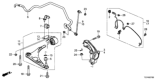
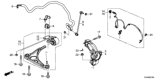
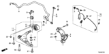
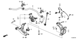
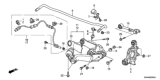
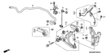
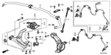
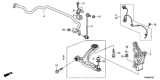
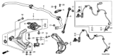
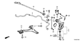
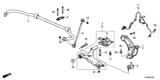
About Honda Control Arm
A part which holds many responsibilities and which is often forgotten about is your Honda control arm. Control arms work by bridging the vehicle frame and the suspension and wheel assembly together. The vehicle frame side of the control arm is connected via bushings, and the other end is attached to the wheel with a specially-sized ball joint. The control arm maintains control of the wheel movement, keeping it to a bare minimum so that it can match the remainder of your entire suspension system for a rigid and tight drive.
Each Honda is different, but the majority of all models will have control arms only at the front of the vehicle. And it is no secret that Honda installs only the finest and longest-lasting parts available, wear and tear can one day take its toll on your control arm, and it will have to be replaced so you can resume safe driving conditions. Know the signs of a faulty unit which can include your steering wheel pulling very hard one way or the other while trying to drive straight, or a very jumpy or choppy steering wheel.
HondaPartsNow.com is proud to deliver the Honda parts and accessories at everyday low prices. We carry an extensive selection of Honda parts, from water pump to oil filter, from brake pad to window regulator, and control arm of course. You will be surprised by the price we offer you because of the huge discount, and the price can be up to 36% off MSRP. You cannot miss such a good chance to save your money and get a genuine brand new Honda part as well. All parts here have a 12-month warranty, so you can just purchase the part with confidence.
Honda Control Arm Parts Questions & Experts Answers
- Q: How to remove and install the control arm and related components on Honda CRX?A:To remove the control arm, first take out the outboard and inboard pivot bolts, then pull the inboard side of the arm down until it clears the body and slide it towards the center of the vehicle until it is free of the hub carrier. Check the bushings at each end of the control arm and the arm itself for any damage or wear. For installation, position the control arm and install the retaining bolts, tightening them to 60 ft. lbs. (83 Nm). For 1988-91 models, raise and safely support the vehicle, then remove the rear wheel and tire assembly. For all models except the Civic Wagon with 4WD, remove the brake drum or rotor, spindle nut, and hub unit, disconnect the parking brake cable and brake line from the wheel cylinder, and remove the brake backing plate. For the 4WD Civic Wagon, remove the brake drum and spindle nut, and disconnect the parking brake cable. Disconnect the brake hose from the brake line and plug it. Support the lower control arm or beam axle with a jack, then remove the trailing arm bushing mounting bolts and disconnect the upper arm and compensator arm from the trailing arm if equipped. For the Civic Wagon with 4WD, remove the rear half shaft outboard CV-joint from the trailing arm using a puller, then remove the trailing arm from the vehicle. Install the trailing arm in position and tighten all bolts and nuts with the vehicle on the ground to ensure proper tightening. Reinstall the half shaft outboard CV-joint if it was removed, reconnect the upper control arm and compensator arm if equipped, and install the trailing arm bushing bolts. Reconnect all hoses and cables to the trailing arm and the brake line, then install the backing plate and any brake components, torquing all bolts to specifications and bleeding the brake system. For the upper control arm, raise and safely support the vehicle, remove the rear wheel and tire assembly, and support the lower control arm or rear axle as necessary. On Accord and Prelude models, remove the cotter pin and castle nut from the upper ball joint, then separate the ball joint from the knuckle using a suitable tool. Remove the upper control arm mounting bolts and the upper control arm itself, then reinstall in reverse order, torquing the bolts with the vehicle on the ground to 29 ft. lbs. (40 Nm) for the control arm-to-body and 40 ft. lbs. (55 Nm) for the control arm-to-trailing arm. For the lower control arm, raise and safely support the vehicle, remove the rear wheel and tire assembly, and if necessary, remove the strut or radius rod mounting bolts from the lower control arm. On Prelude models, remove the cotter pin and castle nut from the ball joint, then separate the ball joint from the knuckle using a suitable tool. Remove the lower arm mounting bolts and the lower control arm, then reinstall in reverse order, tightening the bolts with the vehicle on the ground and torquing the lower control arm-to-body bolt to 40 ft. lbs. (55 Nm) and the control arm-to-trailing arm bolt to 29 ft. lbs. (40 Nm).
- Q: How to remove and install the lower control arm on Honda Del Sol?A:Loosen the front wheel lug nuts, raise the vehicle, place it securely on jackstands, and remove the wheel. Detach the stabilizer bar from the lower control arm. Detach the damper fork from the shock absorber. Remove the cotter pin from the castle nut on the lower balljoint stud, loosen the nut without removing it, and use a puller to separate the lower control arm from the balljoint in the steering knuckle before removing the nut. Remove the pivot bolt from the inner end of the lower control arm and separate the arm from the chassis. Remove the nut from the rear pivot stud, pull the stud out of the bushing, and remove the arm, noting that it's not necessary to remove the three bushing clamp retaining bolts unless the bushing is to be replaced. Installation is the reverse of removal.
- Q: How to remove and install the front upper Control Arm on Honda Prelude?A:To remove and install the upper arm, do not disassemble it; if the ball joint or bushings are faulty, or if the upper arm is damaged, replace the entire upper arm. Begin by safely raising and supporting the vehicle, then remove the front wheels and support the lower control arm assembly with a floor jack. Use needle nose pliers to remove and discard the cotter pin from the ball joint, followed by removing the castle nut. Separate the upper ball joint from the steering knuckle with a ball joint separator tool, then remove the self-locking nuts from the upper arm anchor bolts and take the upper arm out of the vehicle. For installation, use new self-locking nuts for the upper arm and strut, install the upper control arm assembly into the strut tower, and connect the upper ball joint. After installing the front wheels, lower the vehicle and torque the upper control arm nuts to 47 ft. lbs. (65 Nm) and the castle nut to 32 ft. lbs. (44 Nm), tightening it just enough to install a new cotter pin. Finally, tighten the wheel nuts to 80 ft. lbs. (108 Nm) and check the vehicle's front end alignment.
")
")
")
Related Honda Parts
 Honda Control Arm Bushing
 Honda Shift Cable
 Honda Steering Knuckle
 Honda Coil Springs
 Honda Ball Joint
 Honda Lift Support
 Honda Trailing Arm Bushing
 Honda Trailing Arm
 Honda Torsion Bar
 Honda Radius Arm Bushing
 Honda Radius Arm
 Honda Axle Beam
Browse by Model
Accord Control Arm Accord Hybrid Control Arm Civic Control Arm Civic Hybrid Control Arm Clarity Electric Control Arm Clarity Fuel Cell Control Arm Clarity Plug-In Hybrid Control Arm CR-V Control Arm CR-V Hybrid Control Arm CR-Z Control Arm Crosstour Control Arm CRX Control Arm Del Sol Control Arm Element Control Arm Fit Control Arm Fit EV Control Arm HR-V Control Arm Insight Control Arm Odyssey Control Arm Passport Control Arm Pilot Control Arm Prelude Control Arm Prologue Control Arm Ridgeline Control Arm S2000 Control Arm